






Table of Contents
- Key Points
- Understanding Toy Electronics and Voltage Sensitivity
- Case Studies: Analyzing Voltage Response in Different Toys
- Practical Tips for Testing and Troubleshooting Toy Electronics
- Frequently Asked Questions (FAQ)
- Related Questions



Case Studies: Analyzing Voltage Response in Different Toys
Dancing Monkey Toy: A Detailed Voltage Analysis
The dancing monkey toy provides a compelling example of how voltage variations affect toy performance. Typically, this toy is designed to move its limbs and play Music using a motor and a sound module. By varying the voltage, we can observe specific changes in its behavior.

- Normal Operation (3V): At its intended voltage of 3V (two AA batteries), the monkey dances smoothly, and the music plays clearly. The motor operates at a consistent speed, and all functions work in harmony.
- Undervoltage (1.5V): When the voltage is reduced to 1.5V, the monkey's movements become sluggish, and the music may be distorted or absent. The motor struggles to operate, resulting in slow and erratic movements.
- Overvoltage (4.5V - 6V): Increasing the voltage to 4.5V causes the monkey to dance faster, and the music plays at a higher pitch. However, this also introduces the risk of overheating and potentially damaging the motor or sound module. At 6V, the motor may spin uncontrollably, and the circuit components may begin to overheat, leading to premature failure. Overvoltage is not recommended at any circumstance.
By systematically testing the dancing monkey toy at different voltage levels, we can gain insights into the design tolerances and limitations of its electronic components. These observations underscore the importance of adhering to the manufacturer's specified voltage range for optimal performance and longevity.
The Football Player Coin Bank: A Voltage Experiment
The football player coin bank presents another interesting case for voltage analysis. This toy typically kicks a coin into a bank when activated, powered by a motor and a mechanical linkage. The toy is designed to operate with a specific voltage range, and varying the voltage can reveal how well it performs under different conditions.
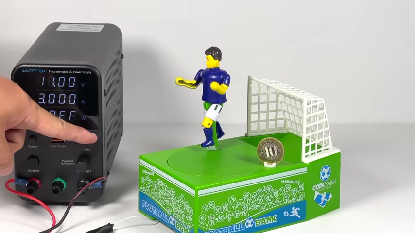
- Normal Operation (3V): At its intended voltage of 3V, the football player kicks the coin reliably, and the mechanism operates smoothly. The motor provides sufficient torque to perform the kicking action without straining the components.
- Undervoltage (1.5V): When the voltage is reduced to 1.5V, the motor may struggle to kick the coin effectively. The mechanical linkage might move slowly or stall, resulting in incomplete or failed kicking attempts.
- Overvoltage (4.5V - 6V): Increasing the voltage to 4.5V causes the football player to kick the coin more forcefully, and the mechanism operates at a faster pace. However, this can also introduce excessive wear and tear on the mechanical components. At 6V, the motor may run at an unsafe speed, and the mechanical linkage might become prone to breakage or malfunction.
Experimenting with the football player coin bank at different voltage levels highlights the delicate balance between performance and component longevity. Adhering to the manufacturer's voltage specification helps ensure the toy operates as intended and avoids unnecessary damage or premature failure.
Duck Escalator: The impact of Voltage Differences
The Duck Escalator toy offers a unique perspective on how voltage affects continuous operation and synchronized movements. This toy uses a motorized escalator to lift small duck figures to the top of a track, where they then slide down a winding path. Analyzing its behavior at different voltages reveals insights into its motor control and synchronization requirements.

- Normal Operation (3V): At its intended voltage of 3V, the escalator lifts the ducks at a steady pace, and the ducks slide smoothly down the track. The motor operates efficiently, and the toy maintains a consistent rhythm.
- Undervoltage (1.5V): When the voltage is reduced to 1.5V, the escalator may struggle to lift the ducks, causing them to move slowly or stall on the incline. The reduced motor power can disrupt the synchronization of the escalator and the duck's descent, leading to operational delays.
- Overvoltage (4V-10V): Increasing the voltage to 4V causes the escalator to lift the ducks faster, and they move down the track at an increased speed. However, this can strain the motor, causing it to overheat or wear out prematurely. At the range between 5V to 7V, the escalator operates more quickly, efficiently and sturdily. However, increasing the voltage to 10V can increase the speed of operation but could possibly damage the machine.
Testing the Duck Escalator at different voltage levels illustrates the importance of stable and consistent power for maintaining synchronized movements. Operating within the manufacturer's recommended voltage range ensures that the toy functions smoothly and reliably, preventing disruptions and component damage.
Singing Dog: Consequences of Varying Voltages
Singing Dog offers interesting consequences of varying voltages when applied on toy electronic circuit. These consequences range from operational deficiency to total damage. The singing dog operates through an electric circuit that helps it carry out basic functions. We will explore the various scenarios.
- Normal Operation (5V): At its intended voltage of 5V, the dog is expected to move its parts and also sing properly without hitches. This allows smooth and effective operation.
- Overvoltage (15V-20V): When the voltage is increased to 15V and 20V, the dog starts dancing erratically while the speech is also not clear. At 20V the dog starts giving out smoke and the dance grows wilder.

The circuits are prone to damage at higher voltages.
- Operational failure (10V): When the voltage is around 10V, the machine does not function the way it is expected to. The moving parts start to lag behind.
- Precautions: These tests were conducted to access the functionality of the machine, it is strongly advised against carrying out such tests.


Most people like






































Report
Please select a reason for reporting
- 13 Reasons to Switch from Snapchat to Text Messaging
- 7 Powerful Speech to Text Apps to Boost Productivity
- 10 Best Speech to Text Tools for Effortless Transcription
- 13 Free Tools to Easily Transcribe Audio to Text
- 15 Surprising Ways Google's Speech-to-Text Boosts Productivity
- 7 Best Free Online Audio to Text Transcription Tools
- 9 Tips to Transcribe Speech to Text Faster and Better
- 13 Best Speech to Text Software for Windows 10 in 2023
- 7 Tips for Choosing the Best Transcriber for Audio to Text
- 11 Reasons Why Dragon Speech-to-Text Apps are Game-Changers
- 6 Secrets to Enhance Your Speech to Text Transcription
- 6 Brilliant Ways to Boost Productivity with Talk-to-Text on Your MacBook
- 6 Ways Transcription Software Converts Audio to Text
- 8 Tips to Transcribe Speech to Text Like a Pro
- 6 Reasons IBM Watson Speech to Text is a Game-Changer
- 14 Powerful Ways Talk-to-Text Improves Your Workflow
- 12 Top Windows Speech-to-Text Software for Efficient Transcription
- 12 Game-Changing Benefits of Apple's Speech to Text Technology
- 9 Powerful Use Cases for AWS Speech to Text Technology
- 10 Easy Steps to Transcribe YouTube Videos to Text
- transcription audio en texte
- online audio transcription
- free audio file transcription
- free ai audio transcription
- audio transcription service
- audio transcription online free
- audio transcription free online
- audio to transcription software
- audio and transcript
- ai audio transcription free
- voice recording to text converter
- translate voice recording to text
- record voice to text
- audio recording to text converter
- voice recording and transcription
- chatgpt voice to text
- gmail voice to text
- speech to text reader
- speech to text ai free
- speech to talk
- Twitter/X API Alternatives for AI Agents and Developers in 2026
- ChatGPT Knows Ford. It Just Doesn't Quote Ford
- Meshy AI: How to Create 3D Models from Text and Images
- How SEO and Marketing Dashboards Empower Agencies to Drive Results
- How to Use AI Tools to Find Internal Linking Opportunities Across a Business Website
- Discover Your Perfect Haircut with AI Hairstyle Apps
- Free Reputation Calculator Tools: How They're Adapting to Score AI Visibility, Not Just Rankings
- Design Professional Flyers for Free on Your Phone
- Best Free Flyer Maker Apps for Android: Design Like a Pro
- How to Know If Your Business Is Ready for an AI Customer Service Agent
- Top 10 AI Marketing Tools Content Creators Need in 2025
- Top 5 Cold Email Software: Maximize Your Outreach in 2025
- Inside Motion Syncr: A Real-World Test of AI Character Animation
- Twitter/X API Alternatives for AI Agents and Developers in 2026
- Your Business Data Could Be Worth Up to $4M. Find Out Without Uploading a Single File.
- Can an eSIM Plan Save You Time During Travel Setup?
- AI Video Editor Review: A Hands-On Look at Prompt-Based Video Editing
- Keep Characters Consistent Across Scenes With Image-to-Video AI
- How to Convert BTC to HNT
- ProxyWing DuckDuckGo Proxy Review: Plans, Setup and Who It Is For

Copyright ©2026 toolify