































Table of Contents
- Key Points
- Understanding Digital Load Cell Code
- Tips for Optimizing Digital Load Cell Performance
- How to Effectively Use a Digital Load Cell
- Advantages and Disadvantages of Using Digital Load Cells
- Frequently Asked Questions (FAQ)
- Related Questions


Understanding Digital Load Cell Code
The Importance of Code Extensions
When working with digital load cells, you'll quickly notice that certain blocks of code are not part of the standard MicroCode library. These blocks, often displayed in a unique color
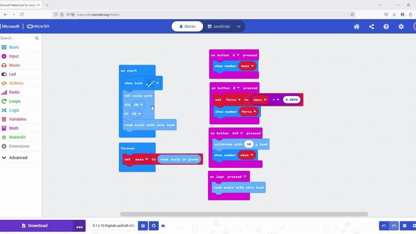
, are associated with specific extensions necessary for the load cell to function correctly. Without these extensions, the code will not be able to communicate with the load cell and interpret its data.
These extensions contain predefined functions and variables that handle the specific communication protocols and data formats used by the digital load cell. This abstraction allows you to focus on the higher-level logic of your project without needing to delve into the low-level technical details of the sensor. Understanding how to incorporate and utilize these extensions is crucial for effectively integrating a digital load cell into your projects. Key components in your digital load cell setup include:
- HX711 Load Cell Amplifier: This amplifier is crucial for amplifying the small signals from the load cell so they can be read by the micro:bit. The HX711 is a precision 24-bit analog-to-digital converter (ADC) specifically designed for weigh scales and industrial control applications to interface directly with a bridge sensor.
- Micro:bit Board: Acts as the main control unit, running the code to read signals from the HX711 and performing necessary calculations or displaying the results. The micro:bit’s processing power and connectivity make it an excellent choice for educational science projects involving load cells.
- Load Cell: Converts force into a measurable electrical signal. Different types of load cells exist, including S-type, cantilever, and button load cells, each suited for different application requirements.
- Connecting Wires: Used to connect the load cell amplifier to the micro:bit, ensuring data transfer and power supply.
Keywords: Digital load cell, micro:bit, code extensions, HX711 amplifier, science projects
Setting Up the Code Environment
Before diving into the code itself, it's essential to set up your coding environment properly. In MicroCode, this means adding the necessary extensions to your project. These extensions provide the specific blocks needed to interact with the digital load cell.
To add an extension, navigate to the extensions menu in MicroCode and search for the appropriate extension for your load cell. Once added, you'll find new blocks available in the toolbox, typically categorized under a specific name related to the load cell or its manufacturer.
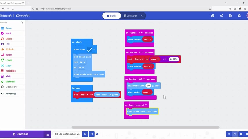
These blocks allow you to set scale pins, read scale data, and perform other essential functions.
The basic steps to setting up the code environment include:
- Opening MicroCode: Navigate to the MicroCode editor in your web browser.
- Adding the Extension: Click on the 'Extensions' tab in the editor, then search and add the extension for the digital load cell. This extension usually contains custom blocks for interacting with the load cell.
- Defining Scale Pins: Use the 'set scale pins' block to define which pins on the micro:bit are connected to the load cell. This step is crucial for establishing communication between the micro:bit and the load cell amplifier.
It's also worth noting that not all extensions are available in the default extension store. Some may require manual import from a URL provided by the manufacturer or community. This process involves copying the URL into the extension search bar and importing the extension from that location.
Keywords: MicroCode, coding environment, extensions, adding extensions, set scale pins
Initial Configuration: On Start Block
The 'on start' block in MicroCode is where you place code that needs to run once when the micro:bit is powered on
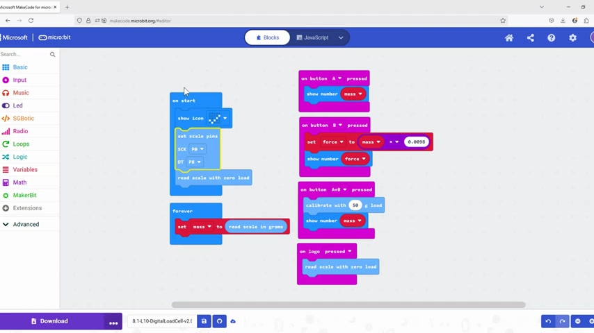
. For digital load cells, this block is used for initial configuration and setup.
Typical tasks performed in the 'on start' block include:
- Displaying an Icon: Show an icon to indicate that the setup process has started. This provides visual feedback that the micro:bit is functioning correctly.
- Setting Scale Pins: Define the pins on the micro:bit that are connected to the load cell. This step is essential for establishing communication between the micro:bit and the load cell amplifier.
- Zeroing the Scale: Read the scale with no load to establish a baseline. This helps to eliminate any initial offset and improve accuracy.
The 'set scale pins' block requires you to specify the pins for the clock and data lines of the load cell. Consult your load cell documentation to determine the correct pin assignments. Once the pins are set, the 'read scale with zero load' block is used to establish a zero point. This process is akin to taring a traditional scale.
        Example On Start configuration:
        show icon [check mark]
        set scale pins (SCK: Pin A, DT: Pin B)
        read scale with zero load
Keywords: on start block, initial configuration, set scale pins, zeroing the scale, MicroCode
Continuous Mass Reading: The Forever Loop
The 'forever' loop in MicroCode allows you to run a set of instructions continuously
. For digital load cells, this loop is used to read the mass from the load cell and update a variable with the current value.
Inside the 'forever' loop, you'll typically find the following:
- Reading the Scale: Use the 'read scale in grams' block to get the current mass reading from the load cell.
- Setting a Variable: Assign the mass reading to a variable, such as 'mass'. This allows you to use the mass value in other parts of your code.
        Example Forever Loop:
        set mass to read scale in grams
The 'read scale in grams' block reads the raw data from the load cell and converts it into a mass value in grams. This conversion is handled by the extension and takes into account the calibration settings of the load cell. Assigning this value to a variable allows you to display the mass on the micro:bit screen, perform calculations, or use it in other parts of your project.
Keywords: forever loop, continuous reading, read scale in grams, setting variables, mass reading
Button-Triggered Actions
The micro:bit has two buttons, A and B, which can be used to trigger specific actions in your code
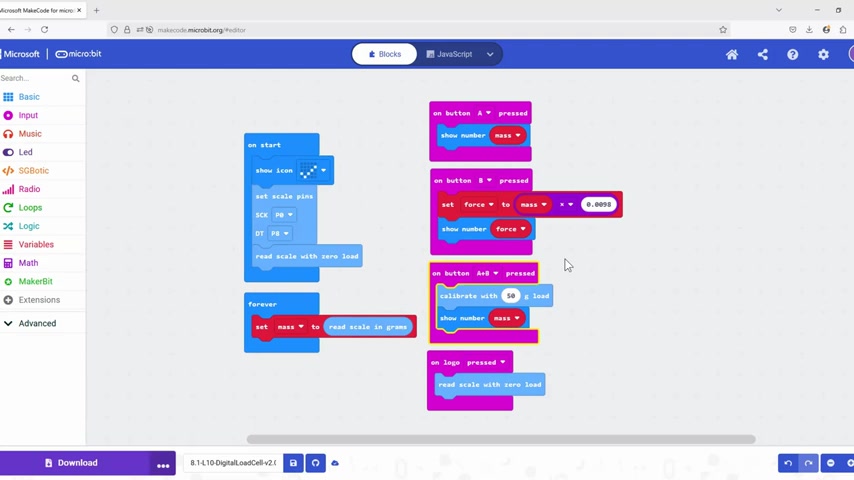
. For digital load cells, these buttons can be used to display mass, display force, or perform other functions.
Common button-triggered actions include:
- Displaying Mass: When button A is pressed, display the current mass reading on the micro:bit screen.
- Displaying Force: When button B is pressed, calculate and display the force acting on the load cell.
- Calibrating the Load Cell: When both buttons A and B are pressed, initiate the calibration process.
        Example Button Actions:
        on button A pressed:
            show number mass
        on button B pressed:
            set force to mass * 0.0098
            show number force
The code for these actions typically involves using the 'on button pressed' block, along with blocks to display numbers, perform calculations, or initiate other processes. The 'set force to mass * 0.0098' line calculates the force in newtons based on the mass in grams. The conversion factor, 0.0098, is an approximation of the acceleration due to gravity (9.8 m/s^2 divided by 1000 to convert grams to kilograms).
Keywords: button-triggered actions, on button pressed, displaying mass, displaying force, calibrating the load cell
Calibration Process: Ensuring Accuracy
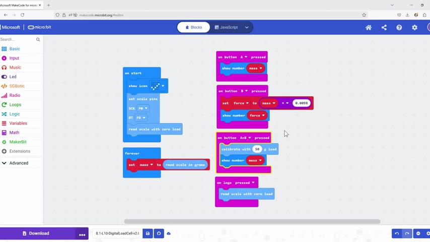
Calibration is a crucial step in ensuring the accuracy of your digital load cell. Calibration involves comparing the load cell's readings to known weights and adjusting the code to compensate for any errors
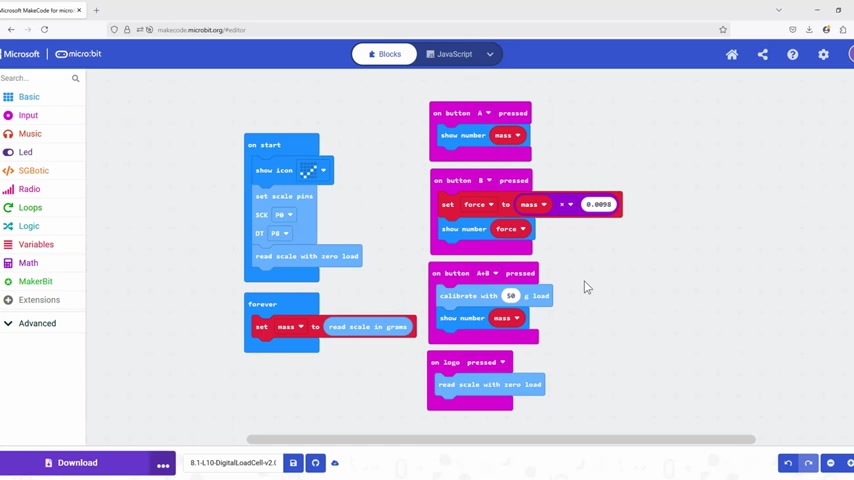
.
To calibrate the load cell, you'll need a set of known weights. The code typically includes a calibration routine that prompts you to place a known weight on the load cell and press a button. The code then reads the load cell's output and calculates a calibration factor to adjust future readings.
        Example Calibration Routine:
        on button A+B pressed:
            calibrate with 50g load
            show number mass
The 'calibrate with 50g load' block initiates the calibration process. This block reads the load cell's output when a 50-gram weight is placed on it and calculates a calibration factor to adjust future readings. Calibration may not be needed, but its a great function to have ready. Ensure your system doesn't suffer from drift or non-linearity. Drift refers to the slow deviation of the output signal over time when a constant load is applied, and non-linearity means that the output signal does not change linearly with the applied load.
It's important to note that calibration should be performed regularly to maintain accuracy. Factors such as temperature, humidity, and mechanical stress can affect the load cell's output over time.
Keywords: calibration process, ensuring accuracy, known weights, calibration routine, calibration factor
Zeroing the Scale: Eliminating Offset
Zeroing the scale is another important step in ensuring accuracy. Zeroing involves reading the load cell with no load applied and subtracting this value from future readings
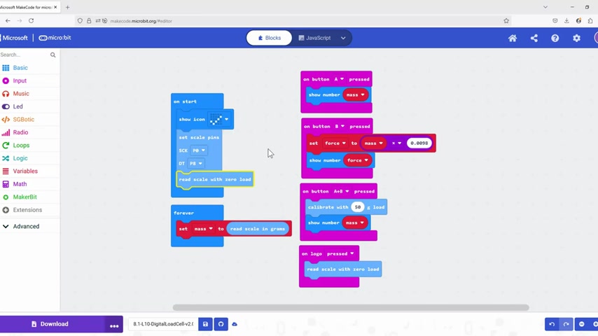
. This eliminates any offset and ensures that the load cell reads zero when no weight is applied.
To zero the scale, you'll typically use a block such as 'read scale with zero load'. This block reads the load cell's output with no weight applied and stores this value in a variable. This value is then subtracted from future readings to compensate for any offset.
        Example Zeroing:
        on logo pressed:
            read scale with zero load
The 'on logo pressed' block allows you to trigger the zeroing process by pressing the micro:bit logo. The 'read scale with zero load' block then reads the load cell's output with no weight applied and stores this value in a variable. This value is then subtracted from future readings to compensate for any offset. You can change how long you need to press the logo from the dropdown menu if you accidentally press it too often!
Keywords: zeroing the scale, eliminating offset, read scale with zero load, micro:bit logo, accuracy








Most people like

































Report
Please select a reason for reporting
- 13 Reasons to Switch from Snapchat to Text Messaging
- 7 Powerful Speech to Text Apps to Boost Productivity
- 10 Best Speech to Text Tools for Effortless Transcription
- 13 Free Tools to Easily Transcribe Audio to Text
- 15 Surprising Ways Google's Speech-to-Text Boosts Productivity
- 7 Best Free Online Audio to Text Transcription Tools
- 9 Tips to Transcribe Speech to Text Faster and Better
- 13 Best Speech to Text Software for Windows 10 in 2023
- 7 Tips for Choosing the Best Transcriber for Audio to Text
- 11 Reasons Why Dragon Speech-to-Text Apps are Game-Changers
- 6 Secrets to Enhance Your Speech to Text Transcription
- 6 Brilliant Ways to Boost Productivity with Talk-to-Text on Your MacBook
- 6 Ways Transcription Software Converts Audio to Text
- 8 Tips to Transcribe Speech to Text Like a Pro
- 6 Reasons IBM Watson Speech to Text is a Game-Changer
- 14 Powerful Ways Talk-to-Text Improves Your Workflow
- 12 Top Windows Speech-to-Text Software for Efficient Transcription
- 12 Game-Changing Benefits of Apple's Speech to Text Technology
- 9 Powerful Use Cases for AWS Speech to Text Technology
- 10 Easy Steps to Transcribe YouTube Videos to Text
- transcription audio en texte
- online audio transcription
- free audio file transcription
- free ai audio transcription
- audio transcription service
- audio transcription online free
- audio transcription free online
- audio to transcription software
- audio and transcript
- ai audio transcription free
- voice recording to text converter
- translate voice recording to text
- record voice to text
- audio recording to text converter
- voice recording and transcription
- chatgpt voice to text
- gmail voice to text
- speech to text reader
- speech to text ai free
- speech to talk
- How to Use AI Tools to Find Internal Linking Opportunities Across a Business Website
- Discover Your Perfect Haircut with AI Hairstyle Apps
- Free Reputation Calculator Tools: How They're Adapting to Score AI Visibility, Not Just Rankings
- Design Professional Flyers for Free on Your Phone
- Best Free Flyer Maker Apps for Android: Design Like a Pro
- How to Know If Your Business Is Ready for an AI Customer Service Agent
- Revolutionizing Storytelling: From Novels to Screenplays with AI
- Create Engaging Animated Explainer Videos with a Free AI Tool
- Stop Multi-Subscribing: Benchmark Top AI Visual Models in One Canvas
- Best Seedance 2.5 API Provider: Every Price on the Market, Checked at Source
- Top AI Social Media Management Tools: Automate Your Content Strategy
- Free AI Text to Video Generator: Create Stunning Videos from Text
- Discover 17 ChatGPT Alternatives: A Comprehensive Comparison
- Character.AI vs. Janitor AI: Which AI Chat Platform Reigns Supreme?
- Top Virtual Assistant Companies in 2026: Reviews, Pricing, and Plans Compared
- Unveiling FaceCheck.ID: Revolutionizing Reverse Image Searches with AI
- 11 Best AI Dialers in 2026: Features, Pricing, Pros and Cons
- How I Direct Consistent AI Clips: A Hands-On Guide to Multi-Model Generation
- A Realistic Review of the Photo Generator Image Tool
- Playwright MCP Server: Automated Web Testing with Agent Mode

Copyright ©2026 toolify